
Moving Baseline Configuration
Moving Baseline is a dual-antenna technique that derives accurate heading (yaw) from two GPS modules on the same vehicle, without relying on the magnetometer. The Orbit Neo Plus supports this feature via its u-blox ZED-F9P chipset and DroneCAN interface.
Overview
Two Orbit Neo Plus units are required — one acts as the Base and the other as the Rover. Both are connected to the flight controller over the same CAN bus. The Base transmits RTCM correction data to the Rover, which computes the precise vector between the two antennas to derive the vehicle’s heading.
Antenna Placement Requirements
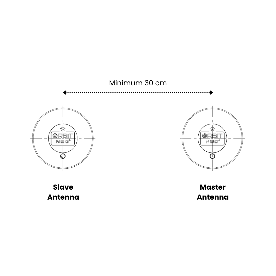
Important: Correct physical placement is critical for accurate heading.
- Both antennas must be separated by at least 30 cm — greater separation yields better heading accuracy
- Mount both units at the same height on the vehicle
- Orient both units with their connectors pointing in the same direction
- Align them front-to-back along the vehicle’s 0° yaw axis (forward direction) for the simplest offset configuration
- Both Orbit Neo Plus units must be on the same CAN bus — use a CAN splitter if needed
Setting Up with ArduPilot Firmware
Prerequisites
- ArduCopter / ArduPilot firmware 4.1.5 or higher
- u-blox ZED-F9P firmware 1.3.2 or higher (pre-installed on Orbit Neo Plus)
- Two Orbit Neo Plus units
- A CAN bus splitter
Connection
- Connect both Orbit Neo Plus units to the same CAN bus on the flight controller using a CAN splitter
- Power the flight controller and connect to Mission Planner
CAN Bus Parameters
Navigate to Config > Full Parameter List and set:
| Parameter | Value | Description |
|---|---|---|
CAN_D1_PROTOCOL | 1 | Enable DroneCAN on CAN1 |
CAN_P1_DRIVER | 1 | Enable CAN1 driver |
GPS Type Parameters
| Parameter | Value | Description |
|---|---|---|
GPS1_TYPE | 22 | DroneCAN moving baseline Base |
GPS2_TYPE | 23 | DroneCAN moving baseline Rover |
GPS_AUTO_CONFIG | 2 | Enable auto-configuration for DroneCAN GPS (required for Moving Baseline) |
GPS_DRV_OPTIONS | 8 | Route RTCM data between the two units via CAN |
EKF and Yaw Source Parameters
| Parameter | Value | Description |
|---|---|---|
AHRS_EKF_TYPE | 3 | Use EKF3 |
EK2_ENABLE | 0 | Disable EKF2 |
EK3_ENABLE | 1 | Enable EKF3 |
EK3_SRC1_YAW | 2 | GPS yaw (use 3 for GPS with compass fallback) |
Note: Do not set
GPS_AUTO_SWITCHto2(Blend) when using Moving Baseline — it is incompatible with this configuration.
Antenna Position Offsets
Set the physical position of each antenna relative to the vehicle’s center of gravity (in meters, FRD frame):
| Parameter | Description |
|---|---|
GPS1_POS_X | Base antenna offset — forward (+) / backward (−) |
GPS1_POS_Y | Base antenna offset — right (+) / left (−) |
GPS1_POS_Z | Base antenna offset — down (+) / up (−) |
GPS2_POS_X | Rover antenna offset — forward (+) / backward (−) |
GPS2_POS_Y | Rover antenna offset — right (+) / left (−) |
GPS2_POS_Z | Rover antenna offset — down (+) / up (−) |
Tip:
GPS1_CAN_NODEIDandGPS2_CAN_NODEIDshow the auto-assigned node IDs after boot. UseGPS1_CAN_OVRIDEandGPS2_CAN_OVRIDEto manually assign which physical unit is Base and which is Rover if needed.
Completing Setup
- Click Write Params after all parameters are set
- Reboot the flight controller
- Point the vehicle at a distant landmark and verify the heading in Mission Planner matches the physical orientation
Setting Up with PX4 Firmware
Prerequisites
- PX4 firmware 1.12.3 or higher
- Two Orbit Neo Plus units
- A CAN bus splitter
Connection
- Connect both Orbit Neo Plus units to the same CAN bus using a CAN splitter
- Connect to QGroundControl
Enable DroneCAN
| Parameter | Value | Description |
|---|---|---|
UAVCAN_ENABLE | 2 | Enable DroneCAN with dynamic node allocation |
Per-Node GPS Configuration
In QGroundControl, navigate to Vehicle Setup > Parameters > DroneCAN and locate each detected ZED-F9P node under its component ID. Configure the following for each node:
On the Base node:
| Parameter | Value | Description |
|---|---|---|
GPS_TYPE | 17 | Moving baseline Base |
GPS_AUTO_CONFIG | 1 | Enable auto-configuration |
On the Rover node:
| Parameter | Value | Description |
|---|---|---|
GPS_TYPE | 18 | Moving baseline Rover |
GPS_AUTO_CONFIG | 1 | Enable auto-configuration |
Set GPS_POS_X, GPS_POS_Y, GPS_POS_Z on each node to reflect the antenna’s physical offset from the autopilot (FRD frame, in meters).
Autopilot Parameters
| Parameter | Value | Description |
|---|---|---|
UAVCAN_SUB_GPS_R | 1 | Subscribe to GNSS relative data from the Rover |
EKF2_GPS_CTRL | 15 | Enable dual antenna heading fusion |
EKF2_GPS_YAW_OFF | 0 | Angle (degrees, clockwise) from Base to Rover — 0 if Rover is directly in front of Base, 90 if Rover is to the right, 180 if behind, 270 if to the left |
Completing Setup
- Write all parameters and reboot the flight controller
- Wait for both units to acquire a GNSS fix
- Verify in QGroundControl that the main GPS enters RTK mode and heading is shown as valid
Verification
Once configured on either firmware:
- The RTK Status LED on both units should indicate a Fixed RTK lock
- The heading reported by the GCS should remain stable and consistent with the vehicle’s physical orientation
- Slowly rotate the vehicle and confirm the heading tracks correctly without compass input