
Moving Baseline Configuration
The Orbit G5 Pro integrates the Septentrio mosaic-G5 P3H, which supports dual-antenna heading natively within a single module. Unlike conventional moving baseline setups that require two separate GPS units, the G5 Pro handles everything internally — you only need to connect two antennas and configure the offsets.
Before You Begin
What You Need
- Orbit G5 Pro
- 2× GNSS antennas
- Flight controller running ArduPilot 4.4.0+ or PX4 1.13.0+
- Mission Planner (ArduPilot) or QGroundControl (PX4)
Antenna Placement Rules
- Minimum separation: 30 cm — greater separation gives better heading accuracy. At 1 m separation, heading accuracy is 0.15°; at 5 m it improves to 0.03°
- Same height — both antennas should be at the same vertical level where possible
- Clear sky view — keep both antennas away from carbon fiber structures, motor arms, and power cables
- Antennas can be mounted in any axis — front-to-back (X), left-to-right (Y), or any combination. The offset parameters must reflect the actual physical placement.
Understanding the Coordinate Frame (FRD)
All offset parameters use the FRD (Forward-Right-Down) body frame:
| Axis | Direction | Positive value means… |
|---|---|---|
| X | Forward–Backward | Component is in front of the reference point |
| Y | Left–Right | Component is to the right of the reference point |
| Z | Up–Down | Component is below the reference point |
Critical: Because Z is positive downward, an antenna mounted above the CG always has a negative Z value. This is the most common setup mistake — always double-check the sign of your Z values.
Step 1 — Physical Connections
- Connect the MAIN antenna to the main antenna port on the Orbit G5 Pro
- Connect the AUX antenna to the auxiliary antenna port
- Connect the 4-pin CAN cable to CAN1 or CAN2 on the flight controller
- Power on the flight controller
Step 2 — Measure and Record Your Offsets
Before configuring any parameters, physically measure three things:
- The horizontal separation between the two antennas (X and Y axes)
- The height difference between the two antennas, if any (Z axis for MB offsets)
- The height of the MAIN antenna above the vehicle CG (Z axis for POS offsets)
Reference Diagram
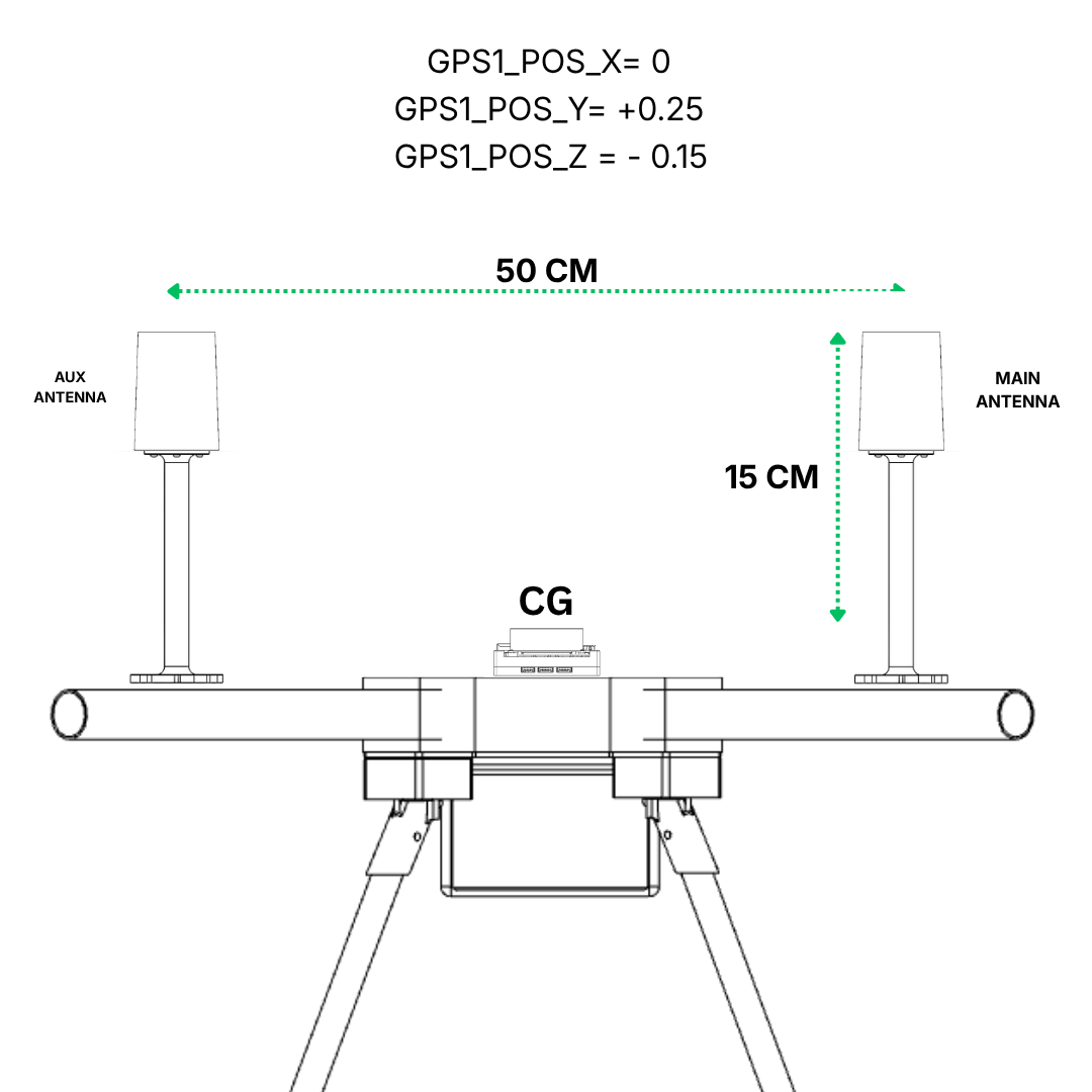
The diagram above shows the typical side-by-side (Y axis) mounting viewed from the rear of the vehicle. The MAIN antenna is on the right side of the vehicle and the AUX antenna is on the left.
A. MAIN–AUX Antenna Offset (GPS1_MB_OFS)
This is the position of the MAIN antenna relative to the AUX antenna.
| Axis | Positive value | Parameter |
|---|---|---|
| X | MAIN is in front of AUX | GPS1_MB_OFS_X |
| Y | MAIN is to the right of AUX | GPS1_MB_OFS_Y |
| Z | MAIN is below AUX | GPS1_MB_OFS_Z |
Values for the reference diagram:
| Parameter | Value | Reason |
|---|---|---|
GPS1_MB_OFS_X | 0.00 | No fore-aft separation between antennas |
GPS1_MB_OFS_Y | +0.50 | MAIN is 50 cm to the right of AUX |
GPS1_MB_OFS_Z | 0.00 | Both antennas mounted at the same height |
Important: Measure center-to-center between the two antennas. A deviation of more than 2 cm from the configured value will prevent heading from being solved.
B. MAIN Antenna Offset from Vehicle CG (GPS1_POS)
This accounts for both the horizontal position of the MAIN antenna and its height above the FC/CG. Both must be measured and entered correctly.
| Axis | Positive value | Parameter |
|---|---|---|
| X | MAIN is in front of CG | GPS1_POS_X |
| Y | MAIN is to the right of CG | GPS1_POS_Y |
| Z | MAIN is below CG | GPS1_POS_Z |
Values for the reference diagram:
| Parameter | Value | Reason |
|---|---|---|
GPS1_POS_X | 0.00 | No fore-aft offset from CG |
GPS1_POS_Y | +0.25 | MAIN antenna is 25 cm to the right of CG (the two antennas are 50 cm apart and the CG is centered between them, so each antenna is 25 cm from CG) |
GPS1_POS_Z | -0.15 | MAIN antenna is 15 cm above CG — negative because Z is positive downward |
Remember: The antennas on a drone are almost always above the CG, so
GPS1_POS_Zwill almost always be a negative value. Entering a positive value would tell the system the antenna is below the CG, which silently degrades positioning accuracy.
Step 3 — Configure Parameters
ArduPilot Setup
Open Mission Planner → Config → Full Parameter List.
3a. Enable DroneCAN
| Parameter | Value | Description |
|---|---|---|
CAN_D1_PROTOCOL | 1 | Enable DroneCAN on CAN1 |
CAN_P1_DRIVER | 1 | Enable CAN1 driver |
3b. Set GPS Type and EKF
| Parameter | Value | Description |
|---|---|---|
GPS1_TYPE | 9 | DroneCAN GPS (use GPS_TYPE=9 for firmware below AP4.6) |
AHRS_EKF_TYPE | 3 | Use EKF3 |
EK2_ENABLE | 0 | Disable EKF2 |
EK3_ENABLE | 1 | Enable EKF3 |
EK3_SRC1_YAW | 2 | GPS heading source — use 3 to allow compass as fallback |
Click Write Params and reboot the flight controller.
3c. Set MAIN–AUX Antenna Offsets via DroneCAN
After reboot, navigate to:
Initial Settings → Optional Hardware → DroneCAN/UAVCAN → mavlink-can1
Click to read the DroneCAN device list, locate the Orbit G5 Pro node, and open its parameters.
If the node does not appear under can1, switch to the Flight Data screen and back, then try mavlink-can2.
| Parameter | Value | Description |
|---|---|---|
GPS1_MB_TYPE | 1 | Enable MAIN–AUX offset entry |
GPS1_MB_OFS_X | 0.00 | No fore-aft separation |
GPS1_MB_OFS_Y | +0.50 | MAIN is 50 cm to the right of AUX |
GPS1_MB_OFS_Z | 0.00 | Both antennas at the same height |
Click Write Parameters then Refresh Parameters to confirm values are saved.
3d. Set MAIN Antenna Offset from CG
Back in the flight controller Full Parameter List, set:
| Parameter | Value | Description |
|---|---|---|
GPS1_POS_X | 0.00 | No fore-aft offset from CG |
GPS1_POS_Y | +0.25 | MAIN antenna is 25 cm to the right of CG |
GPS1_POS_Z | -0.15 | MAIN antenna is 15 cm above CG (negative — FRD frame) |
For firmware below AP4.6, use
GPS_POS1_X/Y/Zinstead ofGPS1_POS_X/Y/Z.
3e. Write and Reboot
- Click Write Params
- Reboot the flight controller
PX4 Setup
Open QGroundControl → Vehicle Setup → Parameters.
3a. Enable DroneCAN
| Parameter | Value | Description |
|---|---|---|
UAVCAN_ENABLE | 2 | Enable DroneCAN with dynamic node allocation |
Save and reboot so the G5 Pro node is detected.
3b. Configure EKF and Heading
| Parameter | Value | Description |
|---|---|---|
EKF2_GPS_CTRL | 15 | Enable dual antenna heading fusion |
EKF2_GPS_YAW_OFF | 90 | MAIN is to the right of AUX — set to 270 if MAIN is to the left |
For other mounting orientations:
| MAIN antenna position relative to AUX | Value |
|---|---|
| MAIN in front of AUX | 0 |
| MAIN to the right of AUX | 90 |
| MAIN behind AUX | 180 |
| MAIN to the left of AUX | 270 |
3c. Write and Reboot
- Save all parameters
- Reboot the flight controller
Step 4 — Verify
LED Check
- The RTK Status LED should be off — indicating Fixed RTK lock
- The blue PPS LED should be blinking at 1 Hz — confirming 3D GNSS fix
ArduPilot — Heading Check
- In Mission Planner switch to the Flight Data page
- In the Status tab, find the
gpsyawvalue - Point the vehicle nose forward and confirm
gpsyawmatches the physical heading - Slowly rotate the vehicle 360° and verify the heading updates correctly throughout
If
gpsyawis always 0, check the following:
GPS1_MB_OFS_X/Y/Zmust be set as node-level DroneCAN parameters, not in the FC parameter list- The center-to-center antenna spacing matches the configured offset within 2 cm
- Both antennas have a clear sky view — indoors or near structures will prevent heading from being solved
PX4 — Heading Check
- In QGroundControl open Analyze Tools → MAVLink Inspector
- Find
GPS_RAW_INTand check theyawfield — confirm it matches the physical vehicle heading - Cross-check with
GLOBAL_POSITION_INT— thehdgvalue should be consistent withGPS_RAW_INTyaw
If the heading appears reversed, flip the sign of
GPS1_MB_OFS_Y(e.g.+0.50→-0.50) or adjustEKF2_GPS_YAW_OFFby 180°.