Pin Configuration
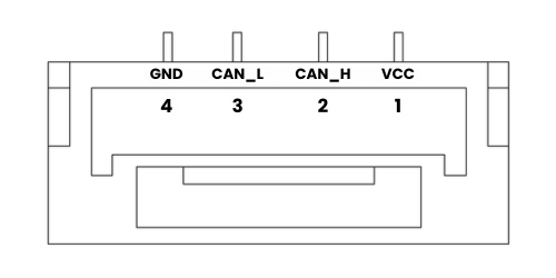
Cable Connection Details
| Pin Number | Function | Cable Color |
|---|
| 1 | VCC_5V | Red |
| 2 | CAN_H | White |
| 3 | CAN_L | Yellow |
| 4 | GND | Black |
LED Status Indicators
The Orbit G5 Pro has two categories of LED indicators — one main LED that reflects the flight controller’s arm/disarm state, and four dedicated small LEDs that indicate the module’s own operational status.
Main LED
The main LED reflects the flight controller status and follows the standard ArduPilot/PX4 LED notification patterns:
Initialization & Basic States
- Alternating Red/Blue Flash: System initialization in progress - keep device stationary
- Pulsing Blue: System ready but no GPS signal acquired
- Steady Blue: System armed, operating without GPS fix
- Pulsing Green: Ready to arm, GPS position locked
- Rapid Green Pulse: Ready to arm, enhanced accuracy with SBAS
- Steady Green: System armed and ready with GPS lock (accompanied by confirmation tone)
Warning States
- Double Yellow Flash: Pre-arm checks failed - verify system settings
- Single Yellow Flash: Radio connection lost
- Yellow Pulse: Battery level critical
- Alternating Yellow/Blue: GPS signal interference detected
- Alternating Red/Yellow: Navigation system error detected
- Alternating Purple/Yellow: Altitude sensor malfunction
Error States
- Solid Red: Critical system error (check SD card status)
- Solid Red with Audio: SD card error or missing
- No LED Activity: Firmware issue or system power problem
Module Status LEDs
Four dedicated LEDs indicate the real-time status of the Orbit G5 Pro module itself.
| LED | Color | Function |
|---|
| PWR | Green | Power |
| PPS | Blue | Pulse Per Second — GNSS timing signal |
| RTK | Orange | RTK fix status |
| ERR | Red | Error |
PWR — Green
| State | Meaning |
|---|
| Solid ON | Module powered and operating normally |
| Off | No power |
PPS — Blue
| State | Meaning |
|---|
| Off | No GNSS fix |
| Solid ON | Powered on, acquiring GNSS signal |
| Blinking (1 Hz) | GNSS 3D fix acquired |
RTK — Orange
| State | Meaning |
|---|
| Solid ON | No RTK — GNSS fix only |
| Blinking | RTK Float — partial correction, limited accuracy |
| Off | RTK Fixed — centimeter-level accuracy active |
ERR — Red
| State | Meaning |
|---|
| Off | Normal operation, no errors |
| Solid ON | Module error — check connections and reboot |
| Blinking | Internal fault — contact technical support |
Additional Notes
- Keep the device stationary during initialization
- Ensure both MAIN and AUX antennas are connected for heading output
- Mount antennas with a clear sky view for optimal signal reception
- Regular system checks recommended for optimal performance
Important: If the ERR LED remains on after reboot, check all CAN connections and verify power supply is stable at 5V. If the issue persists, consult technical support.